14 Results
View results:
Sort by:

Plate girder is an economical choice for long spans construction. I-section steel plate girder typically has a deep web to maximize its shear capacity and flange separation, yet thin web to minimize the self-weight. Due to its large height-to-thickness (h/tw) ratio, transverse stiffeners may be required to stiffen the slender web.

This article shows you how to define different types of member transverse stiffeners in RFEM 6 and RSTAB 9. It also shows you how to consider them in the design as well as the calculation of members with 7 degrees of freedom.
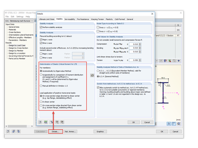
Occasionally, the question arises how to determine the correct load application point of the positive transverse loads in RF-/STEEL EC3 and RF-/STEEL AISC.

In the case of open cross-sections, the torsional load is removed mainly via secondary torsion, since the St. Venant torsional stiffness is low compared to the warping stiffness. Therefore, warping stiffeners in the cross-section are particularly interesting for the lateral-torsional buckling analysis, as they can significantly reduce the rotation. For this, end plates or welded stiffeners and sections are suitable.

To cover the required transverse reinforcement, RF‑CONCRETE Members and CONCRETE determine the most cost-efficient transverse reinforcement as a reinforcement proposal in accordance with the predefined stirrup diameter.

This technical article deals with the stability analysis of a roof purlin, which is connected without stiffeners by means of a bolt connection on the lower flange to have a minimum manufacturing effort.

The design of cold-rolled steel products is defined in EN 1993-1-3. Typical cross-section shapes are channel, C, Z, top hat, and sigma sections. These are cold-rolled steel products made of thin-walled sheet metal that has been cold-formed by roll-forming or bending methods. When designing the ultimate limit states, it is also necessary to ensure that local transverse forces do not lead to compression, crippling of the web, or local buckling in the web of the sections. These effects can be caused by local transverse forces by the flange into the web, as well as by support forces at the supported points. Section 6.1.7 of EN 1993-1-3 specifies in detail how to determine the resistance of the web Rw,Rd under local transverse forces.

In SHAPE-THIN, the calculation of stiffened buckling panels can be performed according to Section 4.5 of EN 1993-1-5. For stiffened buckling panels, the effective surfaces due to local buckling of the single panels in the plate and in the stiffeners, as well as the effective surfaces from the entire panel buckling of the stiffened entire panel, have to be considered.
![Formula Symbols for Connection Between Chords and Web (Source: [1])](/en/webimage/009346/2418256/01-en-3-png.png?mw=640&hash=7a1bc6e87da6f5aeb6d26a130c6ca3dfb6edb8a4)
In order to ensure the effects of panels, which should act as tensile or compression chords, it is necessary to connect them to the web in a shear-resistant manner. This connection is obtained in a similar way as the shear transfer in the joint between concreting sections by using the interaction between compressive struts and ties. In order to ensure the shear resistance, it must be verified that the compressive strut resistance is given and the tie force can be absorbed by the transverse reinforcement.

Composite beams in a three-dimensional analysis are usually connected with orthotropic plates. In that case, the longitudinal direction of the plate stiffness is defined by a main beam and the transverse direction by an orthotropic plate. The stiffness of the plate in the longitudinal direction is set almost to zero. This article explains the determination of stiffnesses in the orthotropic plate.
![System and Loading According to [1]](/en/webimage/009634/2419765/01-en-png-png.png?mw=640&hash=5e657e3feb5c1bb6d21727468dd85d91e1c9f29f)
A structural analysis does not only determine and design internal forces and deformations. It also ensures that the forces and moments in a structure are generated in a reliable way and applied to the foundation. Dlubal Software provides a wide range of products for the structural analysis and design of steel and timber connections. The RF-/JOINTS Steel – Column Base add-on module allows you to design footings of hinged and restrained column bases. The design can be performed for column base plates with or without stiffeners.

The buckling analysis of plates with stiffeners is a special task for engineers. For this, EN 1993-1-5 provides three calculation methods: Effective Cross-Section Method, [1], Sect. 4-7; Reduced Stress Method, [1], Sect. 10; Finite Element Methods of Analysis (FEM), [1], Annex C.

Torsional buckling analysis of transverse and longitudinal stiffeners with open cross-sections is described in DIN EN 1993-1-5, Chapter 9. There is a difference between the simplified method and the precise method, which takes into consideration the warping stiffness of the buckling panel. The simplified method applies Equation 9.3 of DIN EN 1993‑1‑5. If warping stiffness is to be taken into account, either Eq. 9.3 or Eq. 9.4 should be followed. Both design methods are implemented in PLATE-BUCKLING.

In January 2015, DIN Committee NA 005‑08‑23 Steel Bridges applied the introduction of a modification in equation 10.5 of DIN EN 1993‑1‑5. This involves the interaction of longitudinal and transverse pressure in a buckling analysis. Now, the interaction equation provides for auxiliary factor V, which is calculated from the reduction factors of the longitudinal and transverse stresses.